When walking down an aisle in the food store, you see someone drop a can of soup. Although it's a common occurrence—especially for me, I'm a klutz—it's an example of Newton's Law of Gravitation. There's an equation illustrating the law, but to be honest, it doesn't make much sense to me, and I don't want to bore you.
The reason I bring Newton up is to segue into a more extensive discussion about physics. Physics makes the world go around—literally. Examples using the laws of physics are all around the shop, and we mostly don't see them. However, in manufacturing, we use so many pieces of equipment that rely on discoveries by people centuries ago.
Forming metal is a concept that's developed over hundreds of years. However, if it weren't for several brilliant men, who knows just how efficiently we'd be shaping metal.
Metal forming's story is long. Let's start at the beginning.
Our Inability to Stop Changing Things
 Necessity is the mother of invention. For example, if you're getting wet from rain, you build a roof. Think about it, all the fantastic accomplishments and inventions from mankind over our history had to start somewhere.
Roughly 12,000 years ago, hunter-gatherers roamed the land looking for food until they stopped roaming and started farming. The Neolithic Revolution (also known as the Agricultural Revolution) became the groundwork for modern civilization. People began living in single geographic areas and began domesticating plants and animals. What drove people to change? The size of their brains.
Anthropologists credit fire for our oversized brains. The ability to cook food, releasing the nutrients into the body provided advantages to early Homo Sapiens that other members of those branches didn't have. Larger brains led to greater intelligence, which resulted in creating shelter, tools, and weapons.
As history unfolded, many societies began shaping their environments for security and decoration—transitioning from stone materials to metals.
Copper has been used for over 10,000 years ago by people who fashioned the metal into weapons, tools, and decorations. Around 4,000 years later, people added tin to the copper mix, resulting in bronze. As history rolled along, innovation led to processes such as smelting and coking. Throughout this journey, techniques of forming metal into various shapes also evolved.
Blaise Pascal
 Over 370 years ago, a French mathematician and inventor whose work in hydrodynamics became the first step towards an industrial revolution. Blaise Pascal (1623-1662) was a child prodigy, considered one of the greatest mathematicians of all time. Pascal began studying the field of hydrostatics in the 1640s, developing the scientific principles of hydraulic systems.
Pascal Law
After research and testing, Pascal wrote his Treatise on the Equilibrium of Liquids, which illustrated his law of pressure. The Pascal Law states:
...a change of pressure in an incompressible fluid is transmitted equally throughout the fluid. That principle might seem almost intuitively true to us today, but in Pascal's it was a profound insight. An intensely practical man, he applied the principle immediately, inventing the syringe and, more importantly for our industry, the hydraulic press, harnessing the force-multiplying power of the principle he had revealed.
Pascal proved that the application of hydraulic pressure multiplies force. When applying the same amount of pressure to cylinders of differing styles, the larger cylinder has a more significant force output. Repeating Pascal's Law, if pressure increases anywhere within a confined fluid, then there's an equal increase at every other point within the container.
Force Multiplier
Carol Hodanbosi, publishing at the NASA website, explains how force multiplies using hydraulics for lifting a car. Two cylinders are acting as pistons in a sealed system. One cylinder is a square inch in diameter; the other is ten inches. Adding one pound of weight to the smaller cylinder causes the piston to lower the fluid by 10 inches. Because of this force, the larger piston lifts a 10-pound weight 1-inch.
The 1-pound load on the 1 square inch area causes an increase in pressure on the fluid in the system. This pressure is distributed equally throughout and acts on every square inch of the 10 square inch area of the large piston. As a result, the larger piston lifts up a 10-pound weight. The larger the cross-section area of the second piston, the larger the mechanical advantage, and the more weight it lifts.
Joseph Bramah
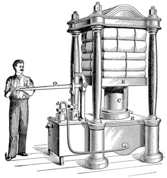 Pascal's work didn't immediately set the industrial world on fire. During the time of his treatise, technology didn't exist for making the precise machining necessary—at least for a century. Around 100 years later, Joseph Bramah (1748-1814) invented the Bramah Press, using Pascal's Law of constant pressure throughout a closed system.
Bramah worked with Henry Maudslay, a young blacksmith, on his press. The 1795 invention could exert enough pressure to several tons to shape heavy steel and iron. This practical application of hydraulics exponentially increased manufacturing capacity.
Each portion of the ram's surface equal in area to that of the plunger; therefore, it receives a like pressure. The difference in the two total areas significantly increases the ram pressure. A force of a few pounds acting on the pump lever can thus be converted into hundreds of pounds-force at the ram.
The hand-operated presses built on this principle are incredibly numerous, for various pressing and forming processes as required in the book-binding, printing, paper, leather, tobacco, tea, drug, jewelry, engineering, and electrical trades. When a larger installation is required, or the powers are high, power-driven pumps are employed, or the supply is taken from accumulators or service mains.
Nevertheless, hand-actuated presses can deliver up to 300 tons of power. Power-actuated types comprise those for punching and shearing, riveting, flanging, forging, bending, baling, bundling, railway wheel forcing, and some particular forms utilized in celluloid, cotton, tube, and munitions manufacture.
The Bramah Press's driving force was to mass-produce a lock he designed, the Bramah Lock, the most secure lock for 60 years. The press produced greater precision, resulting in higher quality.
John Haswell
Another significant contributor to hydraulic presses was Scottish engineer John Haswell (1812-1897). In 1862, his development of a hydraulic forging press was a fundamental change because it was the first machine to forge heavy machine components in dies. The capabilities of his hydraulic forging press led to a broader acceptance of this method of shaping metal.
Despite Haswell's and Bramah's work, the hydraulic press wasn't particularly wide-used. Until the early 1880s, when people needed to shape metal, they did it by hand.
Before machines came along, if someone wanted to bend sheet metal, they'd attach an appropriately sized piece of sheet metal to a mold or a 3D scale model of the desired sheet metal shape; anvil; dolly; or even a forming bag, which was filled with sand or lead shot.
Using a T-stake, ball-peen hammer, a lead strap called a slapper, and tools called spoons, skilled tradespeople pounded the sheet metal into the desired shape, like into the shape of a breastplate for a suit of armor. It was a very manual operation, and it's still performed today in many auto-body repair and art fabrication shops.
Patented in 1882, the cornice brake became the first version of a modern brake, relying on a manually operated leaf which forced a piece of steel to bend. The cornice brake performed simple bends and creases. The first powered press brake relied on the mechanical process created by flywheel-driven machines.
The Second Industrial Revolution witnessed an economic boom. Hydraulic presses were finally introduced to the manufacturing market around 1945 and considered the safer alternative to other forming methods.
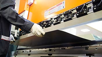
Press Brakes
 Electronic and hydraulic press brakes are the two primary bending methods.
Electronic press brakes are relatively new and offer features not found in hydraulic brakes. Since they're entirely electronic, there's no need for hydraulic fluid, so no leaks. Operating electronic press brakes are smaller because the power draw needed is lower. These brakes are quicker, smaller, and more accurate when the sizes are less than 50 tons.
Press Brake Methods
Writing at the Bystronic Blog, Paul LeTang describes the six most commonly used press drives.
- Mechanical Press
- Conventional Hydraulic Press
- Electrical (Screw) Press
- Electric (Belt) Press
- Servo Hydraulic (Common) Press
- Servo Hydraulic (High-Performance) Press
Mechanical Press
Before 1960, almost all press brakes used mechanical drives. Nowadays, they are only available as used or custom-built.
A typical 3 phase AC motor, flywheel, clutch, brake (where the term Press Brake comes from), and eccentric crankshaft are used to convert electrical energy into linear motion. A treadle or air cylinder is used to disengage the brake and engage the clutch.
The stored kinetic energy in the flywheel is instantly released when the clutch engages. A brake stops the ram after it completes the bend cycle.
Mechanical Press Advantages
- Ideally suited for punching and coining applications
- Fast cycle times; up to 60 cycles per minute
Mechanical Press Disadvantages
- Poor repeatability at lower tonnages
- Requires greater operator skill
- Difficult to limit applied force resulting in overload
- Challenging using CNC controls
- Challenging incorporating safety devices, resulting in a high potential for liability
Conventional Hydraulic Press
Conventional Hydraulic press brakes are older designs and much more common than electrical press brakes. Hydraulic brakes work best with heavier workloads.
Conventional hydraulic presses range from new, low-cost machines and existing presses built before 1980.
A typical 3-phase AC motor and typical hydraulic pump is used to convert electrical energy into fluid power. Hydraulic cylinders and a hydraulic valve system with distinct positions (up, down, high speed, low speed, and stop) is used to convert the fluid power into linear force.
An important point to remember with this configuration is that even on new machines with CNC control, the basic valving system still only has distinct positions, therefore controlled speed ramp down is not possible (go or stop, no taper down).
Because of this limitation, ram repeatability is in the range of +/- 0.002" or about +/- 1 degree bend angle tolerance using a 0.5" V-opening (assuming there are no other variables).
Advantages of Conventional Hydraulic Presses
- It needs only a single fluid power supply powering press and other options
- Low-cost
- A proven method with fewer failures
- The only maintenance needed is monitoring the hydraulic fluid
- Well-suited for applications requiring punching
- The ram speed is broad
Disadvantages of Conventional Hydraulic Presses
- Slow acceleration and deceleration speeds
- Not well-suited for air bending
- There needs to be time for the brake to warm up before the operation
- Open look, ram stopping time variations not compensated
- Torque tube or tape level needs separate manual adjustments
Electrical (Screw) Press
Electrical screw presses use a bidirectional servo motor and ball-screw, which converts electrical energy to linear motion.
Screw Press Advantages
- Inexpensive
- Quick acceleration and deceleration speeds
- Simplistic design
- Very energy efficient
Screw Press Disadvantages
- When applying hydraulic tool clamping options, a motor, pump, and oil tank is needed
- The servo motor is more fragile than a typical 3-phase AC motor
- Gears, belts, screws, nuts, and bearings are expensive and difficult to replace
- Limitations include off-center bending and ram tilting capabilities and available stroke length
Electric Belt Press
A belt press uses a servomotor and a block and tackle pulley system for converting electrical energy into linear motion. A computer and linear encoders control the ram position transition points. The belt and pulley system disperses the bending force across the ram's length.
Belt Press Advantages
- Inexpensive
- Quick acceleration and deceleration speeds
- Simplistic design
- Very energy efficient
- Minimal ram deflection
Belt Press Disadvantages
- When applying hydraulic tool clamping options, a motor, pump, and oil tank is needed
- The servo motor is more fragile than a typical 3-phase AC motor
- Gears, belts, screws, nuts, and bearings are expensive and difficult to replace
- Limitations include off-center bending and ram tilting capabilities

Servo Hydraulic Press Drive
We find servo-hydraulic press drives using high end and ultra-high-end press brakes.
Same features as Servo Hydraulic common, except much higher precision components are used, and much higher repeatability is achieved in the range of +/- 0.0002" or about +/- 0.1 degree bend angle tolerance using a 0.5" V-opening (assuming there are no other variables).
Another auxiliary benefit associated with high-performance hydraulic components is they are also very energy efficient and, sometimes, they consume less energy than the so-called Electrical Press Brakes.
Some Press Brake manufacturers use this high-performance platform to take advantage of other high-end features, such as energy efficiency, improved cycle times and real time machine frame stabilizing.
Servo Hydraulic Press Advantages
- It needs a single, standard fluid power supply
- It doesn't need a warmup period
- The technology is proven with minimal failures
- The only maintenance needed is regarding the hydraulic fluid
- Adapts easily with high-performance options, including energy savers, high speeds, and real-time compensating
- Has a broad speed range
Servo Hydraulic Press Disadvantages
- Not recommended for applications requiring punching
- The initial cost is higher
This is the most recently introduced system with a bidirectional servo motor and bidirectional hydraulic pump used to convert electrical energy into fluid power and control the ram position, direction and speeds. Computer controller and linear encoders are used to control the ram position transition points.
The main improvement over a conventional hydraulic system is that the control valving is minimized and associated valve response times. Ram repeatability is in the range of +/- 0.0002" or about +/- 0.1 degree bend angle tolerance using a 0.5" V-opening (assuming there are no other variables).
Servo Hydraulic (Common) Press
 Common press drives use a 3-phase AC motor and hydraulic pump, which converts electrical energy into fluid power.
Hydraulic cylinders and a hydraulic proportional (the valve opening position is proportional to the distance the ram has to travel) valve system with precision speed and positioning is used to cycle the ram. Computer controllers and linear encoders are used to control the ram position transition points.
The major improvement over a conventional hydraulic system is that the ram stopping time can be monitored and corrected in actual time. Ram repeatability is in the range of +/- 0.0004" or about +/- 0.2 degree bend angle tolerance using a 0.5" V-opening (assuming there are no other variables).
Furthermore, the left/right press drives are totally independent of each other (Y1, Y2). This totally independent bidirectional control system is very advantageous when performing asymmetric bending, typically associated with "staged" bending, where the part is processed on multiple tool stations down the length of the machine. Because the force and positions of the 2 drive cylinders are automatically controlled to balance the bending force on the center of the part, not the center of the ram.
Common Press Advantages
- It needs a single, standard fluid power supply
- It doesn't need a warmup period
- The technology is proven with minimal failures
- The only maintenance needed is regarding the hydraulic fluid
- Best suited for air bending
- Has a broad speed range
Common Press Disadvantage
It's this press brake method we're looking at.
As forming metal using hydraulics became more widely used, several methods eventually became the most common ways of shaping metal. For this article, though, we're sticking to three:
- Coining
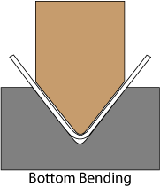
- Bottom Bending
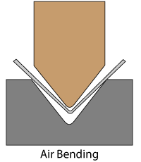
- Air Bending
All three methods use the same type of tool. The key differences between the three are the required bending force and bend precision. As we transition from air bending to bottom bending and bottom bending to coining, the bending force increases.
Regarding precision forming, air bending can't produce precise parts. Coining and bottoming each creates better precision. The problem of springback decreases as we move from air bending to bottom bending or bottom bending to coining.
Coining
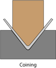 Coining is a cold working process using enormous power to force the metal into predefined shapes. The method of coining derives its name from pressing coins.
When placing numbers, lettering, or images on a coin, a substantial amount of force is needed for placing dents onto the coin. It doesn't matter how many pieces they coin; each bend needs to be precisely the same.
Coining pushes the material down into the bottom die then adds a 10-15% crushing force, locking the piece in the die's angle. This forming method uses the most pressure than other forming methods, typically three to five times greater.
Coining Advantages
- It provides a more refined and better-detailed surface finish
- It provides consistent, accurate bends
- No expensive machinery needed
- No need for complex finishing processes
- No springback
- Forms harder or stronger metal
Coining Disadvantages
- High tonnage needed
- Tooling limitations
- Increased machinery wear
- Larger brakes needed for producing extra pressure
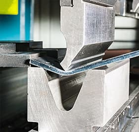
Bottom Bending
Bottom bending forces the metal sheet into a V shape. The angle of the die determines the final angle of the workpiece. As the sheet becomes compressed, it needs more force to complete the process. Using greater force lessens the springback effect, resulting in greater precision.
 Bottom Bending Advantages
- Greater precision than air bending
- Less springback
- It needs less bending force than air bending
Bottom Bending Disadvantages
- Not possible to form a U-shape
- Each angle requires a specific die
- Not suitable for precise parts
Air Bending
Because of its flexibility, air bending is the most common way of forming metal. Air bending forms metal by forcing it into shape by using a top and bottom die. They define the finished angle by three contact points and the depth of the punch. U-shapes are possible using the air bending method.
The punch radius of the top tool and the V angle of the bottom tool need not be the same. In some cases, a square opening replaces the V opening in the bottom tool—especially given today's adjustable bottom tools. The combination of top and bottom tools, therefore, can be applied universally, meaning that with a single combination, various products and profile shapes can be produced simply by adjusting the press-stroke depth. In other words, with a single combination of tools, multiple materials and thicknesses can be bent in a range of bend angles. This makes air bending a highly flexible technique.
It also means that the number of tool changes can be limited considerably, enhancing productivity. Another advantage: Less bend force is required, meaning less bulky tools and resulting in extra allowance in product design.
Although used more; air bending doesn't suit the older forming styles very well because of its error of the mechanism.
Any change in thickness or tensile strength during a run of parts would immediately show up as angular variations in the part. Older hydro-mechanical press brakes had trouble air forming smaller workpieces. They bent the part with the weight of the ram only using the ram's power to return the ram to the top position.
The force of the bending is not encountering the actual "machine thrust" with the excess clearance never being forced out.
 Air Bending Advantages
- Simple process
- The reduced bending force needed
- Less expensive than other methods
- Greater flexibility
- Possible to form very thick sheets
- Able to generate different angles using the same tooling
Air Bending Disadvantages
- The characteristics of the metal have a more significant influence on the finished product
- Finding the correct angle is complicated by springback
- There needs to be an exact punch depth position
Common Press Brake Problems
There are four main issues when using a press brake to form metal:
- Anisotropy
- Springback
- Galling
- Machine Deflection
Anisotropy
Anisotropy describes an object having physical properties with different values in different directions. Because they make the sheets on large, rolling mills, it's exposed to temperature variations to reach its final thickness. Rolling the metal stretches the crystal structure, creating different mechanical properties along its length than found along its width.
During bending, this can lead to variations in the bend angle. Apart from this anisotropic nature, unavoidable variations occur in material properties as a result of minute differences in material composition and rolling conditions. This also results in variations in stress/ strain curves, not only between different batches of sheet materials, but even within a single batch.
Springback
Springback describes the phenomenon where the sheet metal rebounds on either side of the bend once the bending tool lifts.
In the center of the sheet—not exactly the geometrical center, but close to it—resides a zone with low stress in which, even under large bend forces, only elastic deformation occurs. This part of the sheet's cross-section, therefore, wants to return to its original shape after bend force is lifted. The extent to which springback occurs depends on the nature of the sheet material: The stiffer the material, the greater the springback. Soft materials exhibit springback limited to no more than 0.5 deg., and steel to 1 deg., but springback in stainless steel can amount to as much as 3 deg.
Galling
Galling occurs when pieces of material stick to spots on the tooling while bending, resulting in damage to the sheet's surface and the tools.
Machine Deflection
Machine deflection occurs when using high pressure creates lengthwise deflection in the top and bottom dies.
As a result, the top and bottom tools no longer remain parallel during the bend process, bringing variations in the bend angle over the length of the product (Fig. 8). This adversely affects post-bend processes such as robotic welding. In the past, this problem often was remedied by shimming the bottom tool to acquire a crowning that compensated for the deflection. Today, computer-controlled or centrally adjustable crowning systems quickly and accurately compensate for deflection over the entire machine length.
Facts About Hydraulics
A few years ago, the folks at Gerrard Hydraulics compiled a list of 14 little-known facts about hydraulics.
- Hydraulic power is nearly always generated from mechanical power. Example: A hydraulic pump driven by an engine crankshaft.
- Hydraulic power output is nearly always achieved by converting back to mechanical energy. Example: A cylinder, which raises a heavy object.
- There are three types of hydraulic energy: potential or pressure energy, kinetic energy (the energy of moving liquids) and heat energy (the energy of resistance to flow, or friction).
- Hydraulic energy is "neither" created nor destroyed; only converted to another form.
- All energy put into a hydraulic system must come out either as work (gain) or as heat (loss).
- When a moving liquid is restricted, heat is created and there is a loss of potential energy (pressure) for doing work. Example: A tube or hose that is too small or is restricted. Orifices and relief valves are also restriction but are purposely designed into the system.
- Flow through an orifice or restriction causes a pressure
- Oil must be confined to create pressure for work. A tightly sealed system is a must in hydraulics.
- Oil takes the course of least resistance.
- Oil is normally pushed into a pump, not drawn into it. (Atmospheric pressure supplies this push). For this reason, an air vent is needed in the top of the reservoir.
- A pump does not pump pressure; it creates flow. Pressure is caused by resistance to flow.
- Two hydraulic systems may produce the same power output, one at high pressure and low flow, and the other at low pressure and high flow.
- A basic system must include four components: a reservoir to store the oil; a pump to push the oil through the system; valves to control pressure and flow, and a cylinder (or motor) to convert the movement into work.
- Compare the two major hydraulic systems: the open center systems where the pressure is varied but the flow is constant and closed center systems where the flow is varied but the pressure is constant.
Geek Time: TheMandalorian
 I'm a fan of The Mandalorian series on Disney+. The premise is a heavily armed bounty hunter living with a strict code of conduct. If you're knowledgeable about the Star Wars universe, this storyline occurs after the third movie in the original trilogy: Return of the Jedi.
The Mandalorian receives payment as beskar steel ingots; a fictional super-strong metal Mandalorians use for creating their ubiquitous armor. The armor is so strong it deflects blaster shots and strikes from a light saber.
The method they form the armor is a closely guarded secret. Luckily for us, we're able to watch the clan's blacksmith and armorer work on the metal. Yes, it's make-believe, but watching the fictional forming process is pretty cool.
Full Feasibility Study
I'm not the only person thinking this way. Dr. Bart Carleer and Sam Clough, writing at the Forming World site, perform a full feasibility study on forming beskar steel.
Our software created a simple draw die surface and the result from AutoForm-Stamping Adviser ... reveals some red coloring around the ear section of the helmet – demonstrating that certain sharp edges and undercuts featured in the original one-piece design cannot be drawn without any splits. Therefore, I made some geometry modifications in the ear region, shown on the right-hand side of the image. Essentially, I smoothed out some of the radii and eliminated the undercuts in order to make the part feasible for a stamping operation.
"I then performed another feasibility analysis, which showed a significant improvement in this ear region of the helmet. There were some small warning spots remaining, however, which are typically overcome during the next stamping simulation. Actually, in the original helmet from the TV series, these earpieces would not need to be simulated because they are supposed to be separate attachments. However, we wanted a challenging part that could be stamped in a single finished piece.
If you have time, read the full article. The attempt to investigate the fictional armor's formability is fascinating. Plus, if you're able and you're a fan of the Star Wars universe, the storyline is simply and superbly told, light years better than any recent incarnations.

This is the way.
In Sum
As long as we need to shape metal press brakes are needed. There's no getting around this. Brake forming is among the oldest ways of forming metal and considered the workhorse of manufacturing.
It's not glamorous, but our modern world, not the Mandalorian's, wouldn't function without a press brake. Among the industries using a form of hydraulic press brakes are:
- Food industry
- Automotive assembly
- Electrical parts needed for appliances
- Plugs and housings for the electrical industry
- Defense Industry
Using a ball-peen hammer and a torch is no way of going through life.